【www.zhangdahai.com--其他范文】
SUN Shuyi,WEN Geyi
(Research Center of Applied Electromagnetics,Nanjing University of In⁃formation Science and Technology,Nanjing 210044,China)
Abstract: Three design methods for wireless power transmission(WPT)systems using antenna arrays have been investigated.The three methods,corresponding to three common application scenarios of WPT systems,are based on the method of maximum power transmission efficiency (MMPTE)between two antenna arrays.They are unconstrained MMPTE,weighted MMPTE,and constrained MMPTE.To demonstrate the optimal design process with the three methods,a WPT system operating at 2.45 GHz is designed,simulated,and fabricated,in which the transmitting (Tx) array,consisting of 36 microstrip patch elements,is configured as a square and the receiving (Rx) array,consisting of 5 patch elements,is configured as an L shape.The power transmission efficiency (PTE) is then maximized for the three application scenarios,which yields the maximum possible PTEs and the optimized distributions of excitations for both Tx and Rx arrays.The feeding networks are then built based on the optimized distributions of excitations.Simulations and experiments reveal that the unconstrained MMPTE,which corresponds to the application scenario where no radiation pattern shaping is involved,yields the highest PTE.The next highest PTE belongs to the weighted MMPTE,where the power levels at all the receiving elements are imposed to be equal.The constrained MMPTE has the lowest PTE,corresponding to the scenario in which the radiated power pattern is assumed to be flat along with the Rx array.
Keywords: wireless power transmission system;antenna arrays;antenna pattern synthesis;feeding network
The wireless power transmission (WPT) can be traced back to the experiment demonstrated by Nicola TESLA using Hertz’s theory of radio wave transmission[1].During the last decades,the application of WPT technology has been extended to various fields such as the solar power satellite,microwave hyperthermia,implantable devices and electric vehicles[2–3].The WPT systems are usually divided into two categories.One is to use the magnetic induction,for example,two closely spaced coils respectively used as transmitting (Tx) and receiving (Rx);the other is to use two antennas located in the near or farfield region of each other[4–8].
Many efforts have been devoted to enhancing the power transmission efficiency(PTE)for WPT systems and various design criteria have been proposed.Very recently,LI et al.proposed several methods for the design of antenna arrays for a microwave WPT system[9–10].In Ref.[9],a clustering method named thekmeans algorithm was adopted to determine the optimal subarray configuration which yields the maximum beam collection efficiency (BCE).GOWDA et al.demonstrated a WPT system using two patch antenna arrays[11].The excitations of the Tx array are assumed to be equal in amplitude and their phases are properly controlled in order to focus the field at the target plane.The Rx array is designed with dimensions slightly larger than the area of -3 dB region in order to intercept the incident fields while the feeding network for the Rx array is designed with a uniform distribution for both amplitudes and phases.In fact,most previous publications have focused on improving the PTE by adjusting the excitations of the Tx array and ignoring the design of Rx feeding networks.The Rx array is usually connected to a feeding network with a uniform distribution of excitations and the received power is collected at the feeding point[12].Metamaterial,substrate integrated waveguide,and spatial light modulators have also been used in near field multitarget focusing and shaping in complex media[13–15].Algorithms have also been investigated for near-field applications,such as time reversal,phase conjunction,the steepest descent method,Bayesian compressive sensing,and convex optimization[16–18].
Most previous design methods for WPT systems have been demonstrated to be effective.In order to evaluate these methods,a performance index is needed to characterize the WPT systems.Examining all the wireless systems for either information or power transmission,their design has the ultimate goal to maximize the PTE between the Tx and Rx antennas.For this reason,the PTE is made for a performance index to evaluate all the wireless systems.In fact,the PTE may be used as a performance index for all antenna designs.One can make use of the PTE as an objective function to be optimized to design various antenna arrays and WPT systems,and such an optimization process has been referred to as the method of maximum power transmission efficiency (MMPTE)[19–35].For example,a WPT system using a 6×6 patch array as the Tx array and a 4×4 patch array as the Rx array was investigated in Ref.[24],where both the Tx and Rx arrays are optimally designed in terms of MMPTE.The measured PTE reaches 39.4% for a separation distance of 40 cm,which is much higher than a similar design reported in Ref.[11].Recently,the MMPTE has further been applied to the design of antenna arrays to achieve a flattop beam in both near and farfield regions by introducing a constraint to MMPTE so that the power distribution along with the Rx elements is the same.In this case,one needs to solve a quadratically constrained quadratic program (QCQP) problem.By linearizing the QCQP,an analytical solution to the optimal distribution of excitations can be obtained.Based on this procedure,a radio frequency identification (RFID) bookshelf reader antenna array and an RFID antenna array used to track the servers placed in a metal cabinet have been proposed[34–35].Both antenna arrays can generate a wide and flat electric field intensity distribution in the nearfield region and a complicated environment,with a fluctuation of less than 3 dB across the whole shelf,which is much better than previously reported results.A method for adjusting the distribution of the endfire gains in the farfield region of the bidirectional antenna array has also been proposed by introducing a weighting diagonal matrix into the MMPTE[31],where higher gain could be achieved with a smaller array size compared with other similar designs.
Therefore,there have been three different formulations of MMPTE,developed for the design of various antenna arrays.In this paper,the above three formulations will be applied to the design of WPT systems which correspond to three different practical scenarios.The MMPTE,free of weighting coefficients or constraints,will be referred to as unconstrained MMPTE and can be applied to the scenario where the power is transmitted between two antenna arrays without pattern shaping.The MMPTE with a weighting matrix will be referred to as the weighted MMPTE and is suitable for the application where the power levels are required to be different among the receiving elements.The MMPTE with constraints will be referred to as constrained MMPTE and can be applied to the scenario where the radiation pattern must be flat along the receiving antenna elements,e.g.,several closely spaced identical electronic devices are wirelessly powered.For ease of comparison,the three methods will be applied to the design of the same WPT system operating at 2.45 GHz,in which the Tx array consists of 36 patch elements and is configured as a square,and the Rx array consists of 5 patch elements and is configured as an L shape.The Tx and Rx arrays are separated by a distance of 15 cm.The three methods yield three feeding schemes for both Tx and Rx arrays,corresponding to three different application scenarios.
The paper is organized as follows.Section 2 introduces the general power transmission formula between two antennas.Section 3 discusses the three different formulations of MMPTE,which are dedicated to the design of WPT systems.Section 4 describes the design of the aforementioned WPT system,including the selection of antenna elements,the array configurations,the determination of the optimal distribution of excitations,and the design of feeding networks.Section 5 demonstrates the simulation and experimental results,including the nearfield patterns and the realized PTEs for the three different designs.Some conclusions are drawn in Section 6.
Consider a power transmission system consisting of antennas 1 and 2.LetSi(i=1,2) denote the closed surface that encloses antennaionly.When antenna 1 is transmitting and antenna 2 is receiving,the PTE,defined by the ratio of the power received by antenna 2 to the transmitting power of antenna 1[19–20],is given by

whereunis unit outward normal to the surface,andEiandHidenote the fields generated by antennaiwhen antennaj(j≠i) is receiving.The PTE reaches the maximum if the following conjugate matching condition,E1=andH1=-is satisfied,on a closed surface that encloses either antenna 1 or 2.For a WPT system consisting of two planar apertures of regular shapes,the optimization of Eq.(1) yields an eigenvalue equation that can be solved analytically.The eigenvectors of the eigenvalue equation are the optimized aperture field distributions while the corresponding eigenvalues give the PTE[36–39].For two circular apertures of radiusR1andR2separated by a distanceD,a key parameter in the design of the WPT system is(the ratio of two areas)

whereλis the wavelength.It shows that the PTE increases and approaches 100% asCgoes up.Given the requirements of PTE,the transmission distanceD,and the operating frequency,one can use Eq.(2) to determine the minimum aperture sizes to meet the requirements.
The optimized aperture field distribution after optimizing Eq.(1) is a continuous function with a spherical phase distribution and a Gaussianlike amplitude distribution.Physically this implies that the Tx and Rx antennas must focus on each other,which is only possible when the Tx and Rx antennas are in the Fresnel region of each other.
In practice,it is challenging to achieve a continuous aperture field distribution with a single antenna aperture.One possible strategy for addressing the challenge is to approximate the continuous aperture field distribution using an antenna array.The aperture is first discretized into a number of elements,each of which is then replaced by an antenna element.The aperture field may be discretized so that its value over each element is considered a constant and is then used to feed the corresponding antenna element.Such an approach is,however,problematic since the mutual coupling among the antenna elements may cause severe distortion in the radiated field.
Instead of realizing a continuous aperture field distribution via an antenna array,one can directly consider the power transmission between two antenna arrays.The theory of MMPTE between two antenna arrays was first proposed by one of the authors in Ref.[19]in 2010,and has evolved into a powerful and universal method for the design of various antenna arrays during the last decade[20–35].The basic idea behind the MMPTE relies on the recognition that all wireless systems for both information and power transmission have to be optimally designed in the sense that the PTE between Tx and Rx has to be maximized (or minimized if no coupling is allowed between Tx and Rx).Therefore,by properly introducing a test receiving antenna array,the optimal design of antenna arrays reduces to the optimal design of WPT systems,and the best possible antenna performance is thus guaranteed.
A WPT system consists ofmTx antenna elements andnRx antenna elements,which forms an (m+n)-port network enclosed by the small dotted rectangle in Fig.1,and it can be characterized by the scattering parameters as follows
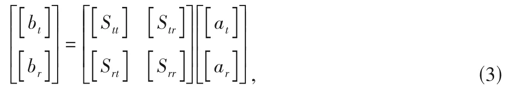
where the subscripttandrrespectively stand for Tx and Rx,and

respectively denote the normalized incident and reflected waves for the Tx array and the Rx array.The PTE,denoted byT,between Tx and Rx arrays is defined as the ratio of the total power delivered to the Rx array to the input power into the Tx array.Assuming that both the Tx and Rx arrays are well matched (a general discussion for a nonmatched system can be found in Ref.[21]),we have[19–21]:

where[A]=[Srt]H[Srt]is a matrix determined by the scattering parameters of the whole system and the superscriptHdenotes the Hermitian operation.
3.1 Unconstrained MMPTE
When the PTE defined by Eq.(5) is required to be stationary,an eigenvalue equation can be obtained as follows[19–20]

where the largest eigenvalue gives the maximum PTE,and the corresponding eigenvector [at] gives the optimal distribution of excitations for the Tx array.Once the optimal distribution of excitations for the Tx array is known,the optimal distribution of excitations for the Rx array is then given by

The above procedure does not involve any constraint and is therefore referred to as unconstrained MMPTE (UMMPTE).With one test receiving antenna placed in the direction where the radiation intensity needs to be maximized or minimized,the UMMPTE can be used to design focused antennas[22–26],smart antennas[27–30],and endfire antennas[31].

▲Figure 1. Equivalent network
It can be shown that the optimized distribution of excitations obtained from Eq.(6) becomes uniformly distributed in both amplitude and phase if the Tx and Rx arrays are in the farfield region of each other.In order to avoid this trivial case,one must properly select the aperture size for both Tx and Rx arrays so that they are in the Fresnel region of each other.
3.2 Weighted MMPTE
The second formulation of the MMPTE introduces a weighting matrix [W]=diag(w1,w2,...,wn) to achieve a prescribed power distribution among the Rx elements in the near or farfield region.In this case,the received power distribution by the Rx elements is modified by the weighting matrix as follows

Replacing [br] in Eq.(4) with [b"r] and following the same procedure as UMMPTE,we obtain the distribution of excitations for the Tx array,which will generate the desired power distribution among the Rx elements as prescribed by the weighting matrix[W].The above procedure is called weighted MMPTE (WMMPTE).For example,the weighting matrix can be properly selected so that the power levels at all the receiving elements are identical.

The optimal distribution of excitations for the Rx array is then given by

By adjusting the weighting matrix [W],the radiation pattern can also be shaped according to a prescribed manner.For example,the WMMPTE can be used to design multiple beam antennas[31].
3.3 Constrained MMPTE
A constraint can also be introduced to MMPTE to realize the desired field pattern in the nearor farfield region.In this case,one needs to solve a QCQP problem.For example,in order to achieve a uniform electric field distribution along with the Rx elements,the PTE can be maximized with the following constraints

which guarantees that the radiated field from the Tx array is equally distributed along with the Rx array elements.We also introduce anndimensional weighting diagonal matrix [W].Then the following equivalent normalized quadratic optimization problem with linear constraints can be obtained:

where [y] represents anndimensional vector,the element value of which is a constant.By using the method of Lagrange multiplier,the optimized distribution of excitations can be obtained as follows[35]:

The optimal distribution of excitations for the Rx array is given by Eq.(7).The constrained MMPTE (CMMPTE) can be used to shape radiation patterns in various complicated environments[34–35].
The UMMPTE,WMMPTE,and CMMPTE are naturally applicable to the design of WPT systems,and they are all optimal in a certain sense and correspond to three different application scenarios of WPT systems as mentioned above.The three optimization methods will now be applied to the design of the same WPT system so that a comparison can be easily made.As shown in Fig.2(a),the antenna element used for both Tx and Rx arrays is a coaxialfed square patch.The reflection coefficient of the patch element is shown in Fig.2(b),and the antenna element is resonant at 2.45 GHz.As illustrated in Fig.3,the Tx array consists of 36 elements,equally spaced with a separation of 0.5λ(λis the wavelength of 2.45 GHz in free space) and arranged as a square shape and built on a 3 mmthick FR4 substrate (relative permittivity ofεr=4.4,and loss tangent of 0.02).The Rx array consists of 5 elements,arranged as an L shape with a separation distance of 1.25λand also built on a 3 mmthick FR4.Here an L shape for Rx array is purposely selected so that its elements are off the center line of the Tx array to make the design more challenging.The separation between the Tx and Rx arrays is 15 cm.After including the feeding systems,the (36+5)-port power transmission system can be considered a twoport network enclosed by the large dotted square in Fig.1.

▲Figure 2. (a) Element of antenna arrays and (b) simulated and mea⁃sured reflection coefficient of the Tx array
Once the WPT system is set up,the scattering parameters for the (36+5)-port network can be obtained either by simulation or by measurement.In this paper,the simulation tool Ansys HFSS is used to determine the network parameters.For ease of comparison,three application scenarios are considered.The first scenario corresponds to UMMPTE,where no pattern shaping is required on the Rx side.The second scenario corresponds to WMMPTE,where the received power levels at the Rx elements are constrained to be identical.The third scenario corresponds to CMMPTE,where the radiated field pattern along with the Rx array is constrained to be flat.For WMMPTE and CMMPTE,a weighting matrix [W] is introduced and adjusted to ensure that the constraints are achieved.For the WPT system shown in Fig.3,the weights for WMMPTE and CMMPTE are listed in Table 1.
The optimized distributions of excitations for the Rx and Tx arrays in the three application scenarios can be obtained from Eqs.(5)–(8),and are listed in Tables 2 and 3 respectively.It can be seen from Table 2 that the optimized distribution of excitations for Rx arrays obtained from WMMPTE and CMMPTE has a uniform amplitude distribution,and the phase distribution for CMMPTE is also uniform.The three feeding networks for the Rx arrays can be built from Table 2,and they are illustrated in Fig.4.Based on Table 3,the three feeding networks for Tx arrays can be built and are illustrated in Fig.5.All the feeding networks have been built by the transmission line theory.The amplitude distribution of the feeding network is controlled by the power dividers while the phase distribution is controlled by the length of the feeding line.Note that one can ignore those patch elements with very small amplitudes of excitations during the design of the feeding networks.For example,the patch elements 3,4,5,6,9,12,18,and 23 in UMMPTE are insignificant and can thus be neglected.Since too many details are involved,the dimensions of the feeding networks are not labeled in Figs.4 and 5.

▲Figure 3. Wireless power transmission(WPT)system

▼Table 1. Weights for CMMPTE and WMMPTE

▼Table 2. Optimized distribution of excitations for Rx arrays

▲Figure 4. Feeding networks for Rx arrays:(a) UMMPTE,(b)WMMPTE and(c)CMMPTE

▼Table 3. Optimized distribution of the excitations for Tx arrays
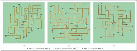
▲Figure 5. Feeding networks for Tx arrays:(a)UMMPTE,(b)WMMPTE,and(c)CMMPTE
In practice,the design of a WPT system must meet the PTE requirement for a given transmission distance.The PTE depends on a number of factors,including the antenna elements,element spacing,transmission distance,aperture size,substrate material,environment,and array configurations.The design procedure of the WPT system using antenna arrays can be summarized as follows.
1) Set up the WPT system.According to the PTE requirement and transmission distance,one needs to determine the aperture sizes of both Tx and Rx arrays so that they are in the Fresnel region of each other.The antenna elements,the interelement spacing,and array configurations can be determined by the application scenarios.
2) Determine the scattering parameters.Once the WPT system is set up,one needs to determine the proper weighting coefficients to achieve the desired radiation pattern.The scattering parameters can be obtained by simulation or by measurement.It is noted that the scattering parameters contain all the information about the WPT system,including mutual couplings,array configuration as well as environments.
3) Find the optimal distribution of excitations for the array elements.The optimal distributions of excitations for Tx and Rx arrays can be determined from Eqs.(5)– (8).For UMMPTE,one needs to solve an eigenvalue equation;for WMMPTE and CMMPTE,the optimal distribution can be obtained analytically.
4) Build the feeding networks.The feeding networks for both Tx and Rx arrays can be built from the optimized distribution of excitations using the transmission line theory.The amplitude distribution is achieved by power dividers and the phase distribution is controlled by the lengths of the feeding lines.
The setup of the WPT system is shown in Fig.6.Both the Tx and Rx arrays are connected to a dedicated feeding network to realize the optimized distribution of excitations so that the highest PTE can be reached under three different application scenarios.The input power to the Tx array is set to 30 dBm and is provided by a radio frequency (RF) amplifier connected to a signal generator.The normalized field patterns generated by the three Tx arrays are respectively plotted in Figs.7 (a),7(b),and 7(c),and the numerical values of the received power at the spots where the test receiving antenna elements reside are listed in Table 4.
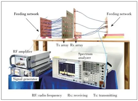
▲Figure 6. Setup of wireless power transmission(WPT)system

▲Figure 7. Simulated electric field patterns from (a) unconstrained MMPTE (UMMPTE),(b) weighted MMPTE (WMMPTE),and (c) constrained MMPTE(CMMPTE)
For UMMPTE,the received power is not evenly distributed along with the receiving elements,and the received power level at ports 38 and 40 is significantly higher than the rest,which guarantees that the total power received by the Lshaped Rx array is maximized.For WMMPTE and CMMPTE,the fluctuation of the received power distribution is less than 1 dB along with the receiving elements.Note that the received power obtained from CMMPTE is lower than that obtained from WMMPTE.The reason is that the former requires that the radiated power pattern is flat along with the receiving elements while the latter only requires that the received power levels at the receiving elements are all equal.
The total measured losses of the three sets of feeding networks (Tx combined with Rx) are 3.5 dB,3.6 dB and 3.5 dB,respectively.The measured transmission coefficients of the twoport system defined by the large dotted square in Fig.1 are plotted in Fig.8 and the values of|S21|for the three application scenarios are -10.1 dB,-11.7 dB and -13.1 dB at 2.45 GHz,respectively.The transmission coefficientS21of the twoport network can be used to calculate the power transmission efficiencyTof the WPT system including the feeding networks through

In terms of Eq.(14),the measured PTEs of the system arefound to be 21.8%,14.8%,and 10.7%respectively.The simulation and measured PTEs are listed in Table 5,and they are compared with the usual design with uniform distribution of excitations for both Tx and Rx (i.e.,without optimization).The PTE of the latter is only 2.2% and is significantly lower than the three optimized results.The highest PTE is given by UMMPTE since it does not involve any constraints.The lowest PTE is given by CMMPTE as it requires that the radiated energy is equally distributed along the whole path of the Lshape,while WMMPTE only requires that the radiated energy is equally distributed at the locations where the Rx elements are placed.

▼Table 4. Received power distributions at spots where the receiving an⁃tennas are positioned

▲Figure 8. Measured|S21|of the wireless power transmission(WPT)system
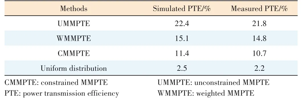
▼Table 5. Comparison of PTEs
Three application scenarios for the WPT system have been investigated by MMPTE,which respectively correspond to the unconstrained MMPTE,the weighted MMPTE,and the constrained MMPTE.The three application scenarios have been implemented by the same WPT system,in which the Tx array consists of 36 microstrip patch elements and is configured as a square while the Rx array consists of 5 patch elements and is configured as an L shape.The WPT system,operating at 2.45 GHz,is designed,simulated and prototyped.The first scenario does not put any constraints on the radiated field patterns;the second scenario requires that the received power levels at all Rx elements are equal;the third scenario requires that radiated field pattern along the Rx array is flat.By maximizing the PTE between the Tx and Rx arrays,the optimized distributions of excitations for both Tx and Rx arrays are obtained analytically or by solving an eigenvalue equation.Based on the optimized distribution of excitations,the feeding networks for both Tx and Rx can be built by using the theory of the transmission line.Simulation and experimental results indicate that the first scenario,where no constraints are involved,yields the highest PTE.The last two scenarios are seldom studied in previous publications.
The three optimization methods proposed for the design of WPT systems apply to any environment and any antenna array.The weighted MMPTE and the constrained MMPTE can be used to achieve various field patterns or power distributions on the Rx side of the WPT systems,and at the same time to maintain the highest possible PTE.
It is noted that the MMPTE can be formulated in terms of other circuit parameters such as the impedance parameters or admittance parameters,and the discussions are the same as for the scattering parameters[40].
本文来源:http://www.zhangdahai.com/shiyongfanwen/qitafanwen/2023/0603/606361.html